Hesheng Cable

Leave Your Message
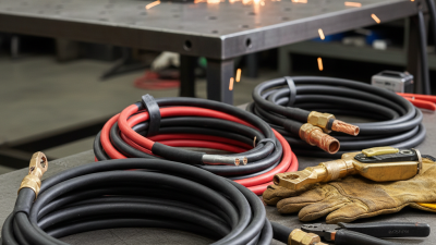
Welding Cable is the flexible, high-current conductor that connects a welding power source to the electrode holder, work clamp, or feeder. It may look simple, but its design affects arc stability, heat control, and jobsite safety. A typical cable uses finely stranded copper, rubber or thermoplastic insulation, and a jacket built to resist abrasion, oil, sparks, and repeated bending.
The American Welding Society highlights proper cable selection, secure connections, and regular inspection as practical parts of welding safety. The National Fire Protection Association also stresses controlling electrical and fire hazards around welding operations. Market reports from Grand View Research and MarketsandMarkets indicate continued growth in welding equipment and industrial fabrication, driven by construction, automotive production, shipbuilding, and infrastructure projects. Cable demand follows these applications, although published market figures vary by scope and region.
Jody Collier, a widely recognized welding educator, puts the practical issue clearly: “Your welding cable is only as good as the connections on each end.” That principle deserves attention. A damaged jacket, loose lug, or undersized cable can create voltage drop, excess heat, and frustrating arc performance. The cable may not be the most visible tool in a welding setup. It remains essential.
Choosing Welding Cable requires more than matching amperage. Cable length, duty cycle, ambient temperature, flexibility, and connector quality all matter. Some specifications seem precise, but field conditions are rarely perfect. This guide explains what Welding Cable is, how it works, where it is used, and how professionals can select and maintain it more reliably.
What Is Welding Cable and What Is It Used For?
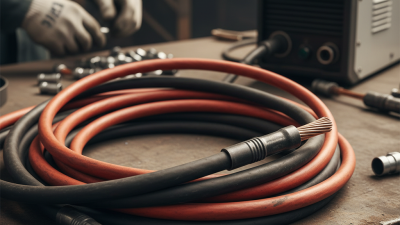
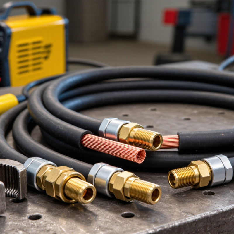
A 600 V welding cable carries current between the welding machine, electrode holder, and work clamp. The 600 V marking describes insulation capability, not the recommended welding current. It bends easily. Its conductor uses many fine, flexible copper strands, usually arranged in concentric layers under ASTM B8 principles. This construction reduces bending stress around a crowded workbench or a sharp machine connection. A durable elastomer jacket can resist abrasion, heat, and occasional contact with welding spatter. However, jacket performance depends on its material and temperature rating.
Cable selection requires more than reading the voltage label. NFPA 70, 2023, Article 630, addresses conductor sizing for welding equipment and recognizes duty-cycle conditions. IEC 60974-1 uses a ten-minute reference period for welding-machine duty cycle. For example, a 60% duty cycle means six minutes of rated operation within ten minutes. That figure affects heating and practical ampacity. Longer leads create voltage drop, while bundled cables retain more heat. A practical inspection should check flattened insulation, exposed copper, stiff sections, and loose terminals. The shortcut is tempting: choose the thickest cable available. That can still be wrong. The correct choice considers current, lead length, duty cycle, ambient temperature, and connector compatibility. A cable may look healthy outside while heat damage develops beneath its jacket.
| Data Dimension | Typical Specification | Technical Description and Practical Use |
|---|---|---|
| Cable Definition | Flexible single-conductor power cable | Welding cable is a highly flexible electrical cable designed to carry current between a welding power source, electrode holder, work clamp, and the workpiece. |
| Voltage Rating | 600 V maximum rated voltage | A 600 V rating identifies the maximum system voltage for which the cable insulation is designed. The cable must still be selected and installed according to the equipment instructions and applicable electrical codes. |
| Conductor Material | Annealed copper | Copper provides high electrical conductivity and good resistance to repeated bending. Annealing softens the copper and improves flexibility compared with harder conductor constructions. |
| Conductor Construction | Numerous fine copper strands | Fine stranding allows the cable to bend repeatedly without becoming excessively stiff. Common constructions use concentric or rope-lay arrangements, with the exact strand count depending on conductor size and flexibility class. |
| Common Conductor Sizes | Approximately 6 AWG to 4/0 AWG | The required size depends on welding current, cable length, duty cycle, allowable voltage drop, ambient temperature, and installation method. Larger conductors generally reduce voltage drop and heating. |
| Current Capacity | Application-dependent; commonly rated by welding duty cycle | Welding cable ampacity is not determined by conductor size alone. Published current ratings may vary for 100%, 60%, 50%, or 30% duty cycles. Always use the rating table supplied for the specific cable construction. |
| Insulation Material | Flexible thermoset or thermoplastic insulation | Common insulation families include neoprene-type, EPDM-type, and other flexible rubber or elastomeric compounds. The material is selected for flexibility, abrasion resistance, oil resistance, and temperature performance. |
| Typical Temperature Range | Often approximately −40°C to +90°C, depending on construction | The actual minimum and maximum operating temperatures vary by insulation system. The cable should not be used outside its marked temperature rating or in conditions that can damage the jacket. |
| Outer Jacket Characteristics | Flexible, abrasion-resistant, and impact-resistant | The outer covering protects the conductor from mechanical wear caused by dragging, coiling, bending, and contact with workshop surfaces. Resistance to oil, sunlight, chemicals, and cuts depends on the jacket compound. |
| Polarity and Circuit Function | Electrode lead or work-return lead | One cable connects the welding power source to the electrode holder or torch. Another cable connects the power source to the work clamp and completes the welding circuit. |
| Primary Welding Processes | SMAW, GMAW, FCAW, and GTAW applications | Welding cable is used with stick welding, gas metal arc welding, flux-cored arc welding, and gas tungsten arc welding equipment when the cable size and current rating match the process requirements. |
| Other Applications | Battery systems, power distribution, and flexible grounding connections | The same flexible construction may be used for battery interconnections, temporary power connections, mobile equipment, grounding leads, and other low-voltage high-current applications when the cable rating is suitable. |
| Cable Length Selection | Shorter lengths are preferred when practical | Longer cable runs increase resistance and voltage drop. If a long run is necessary, a larger conductor may be required to maintain welding performance and limit heat generation. |
| Flexibility Advantage | High flexibility compared with ordinary building wire | The combination of fine copper strands and flexible insulation allows the cable to follow the operator’s movements and withstand frequent coiling. It is intended for repeated flexing rather than permanent rigid installation. |
| Important Limitation | Not automatically interchangeable with every power cable | A welding cable should not be substituted for building wire, portable cord, or machine cable unless its voltage rating, temperature rating, current capacity, environmental performance, and applicable approvals satisfy the installation requirements. |
| Inspection Requirements | Check insulation, terminals, connectors, and exposed conductor | Remove damaged cable from service when the insulation is cut, burned, crushed, excessively worn, or separated from a connector. Loose or overheated terminals can create high resistance and dangerous localized heating. |
| Selection Checklist | Size, length, duty cycle, environment, and connector compatibility |
|